Cable & Wire | Good quality and good service based on reasonable prices.
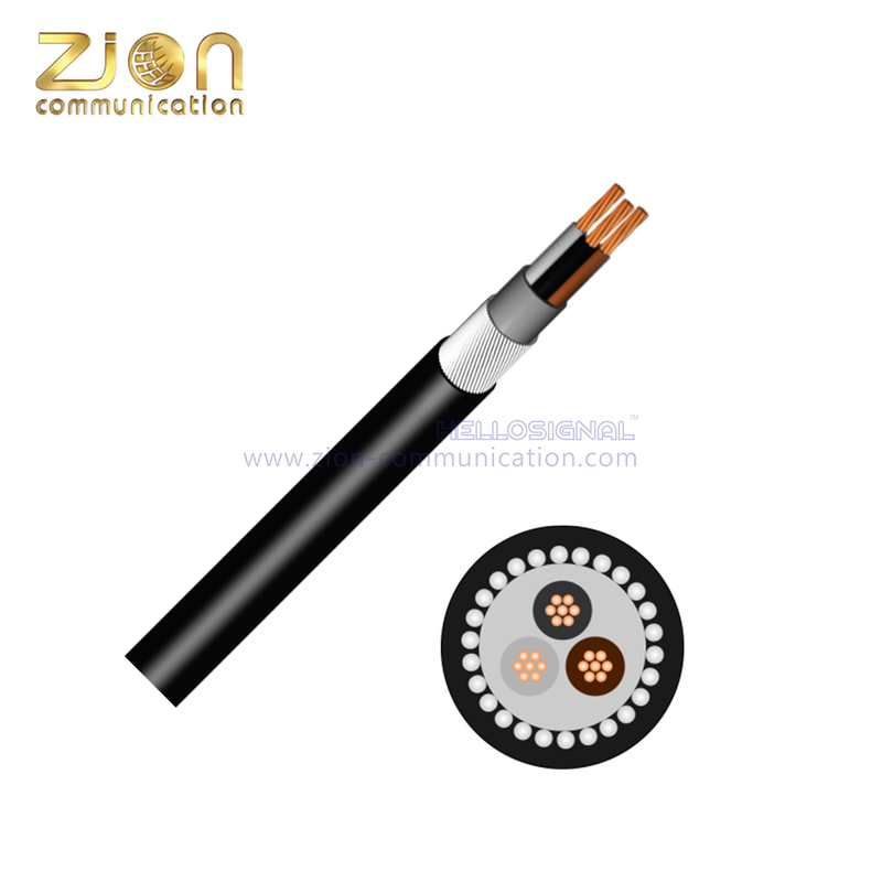 |


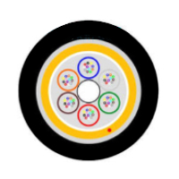
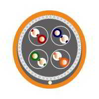
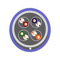
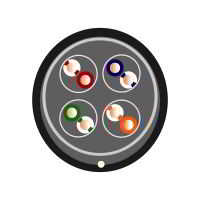
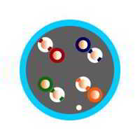
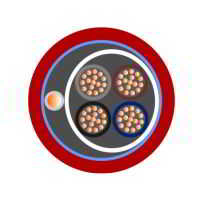
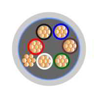
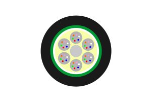
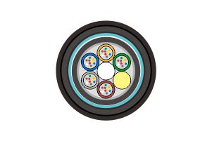
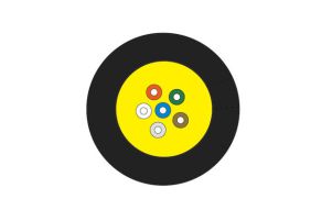
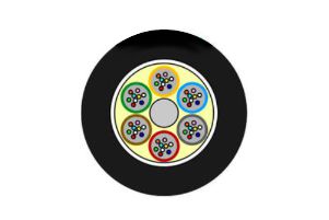
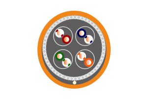
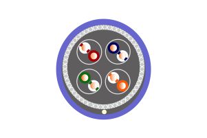
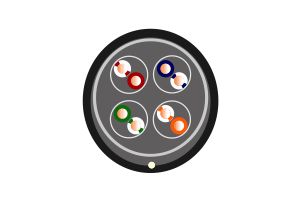
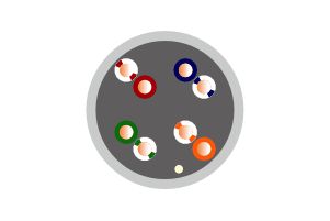
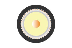
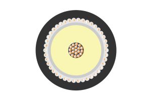
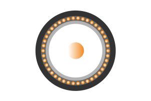
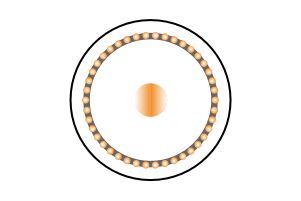
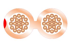
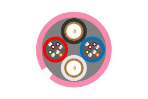
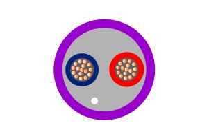
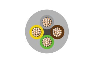
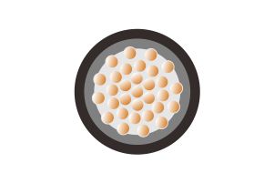
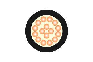
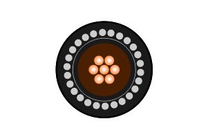
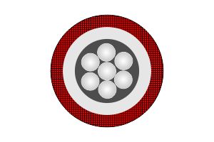
CU/XLPE/LSZH/SWA/LSZH 0.6/1KV Cable(1.5mm²-16mm²)
hellosignal
Product Description
CU/XLPE/LSZH/SWA/LSZH 0.6/1KV Cable(1.5mm²-16mm²) | |||||||||||||||||||
| |||||||||||||||||||
Application: | Cable Standards: | ||||||||||||||||||
Used in power networks, indoor, outdoor, underground. Can be used in cable ducting for installation where fire, smoke emissions and toxic fumes create a potential threat to life | BS6724, Acid gas emission to BS EN 50267 (IEC 60754-1) | ||||||||||||||||||
Smoke emission to BS EN 50268 (IEC 61034) | |||||||||||||||||||
Flame propagation: IEC 60332-1, IEC60332-3, | |||||||||||||||||||
Product Description: | |||||||||||||||||||
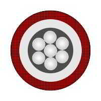
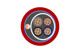
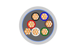
Conductor | Plain Annealed Stranded Copper Conductors | ||||||||||||||||||
Insulation | Cross linked Polyethylene (XLPE) | ||||||||||||||||||
Bedding | LSZH | ||||||||||||||||||
Armour | Galvanised Steel Wire Armour | ||||||||||||||||||
Sheath | Low Smoke and Zero Halogen | ||||||||||||||||||
Characteristics: | |||||||||||||||||||
Voltage Rating | 600/1000 Volts | ||||||||||||||||||
Temperature Limits | -25°C to +90°C | ||||||||||||||||||
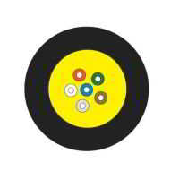
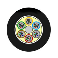
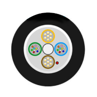
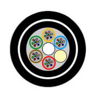
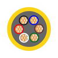
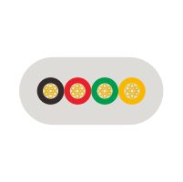
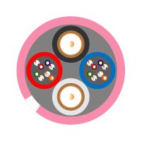
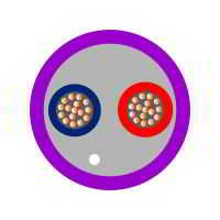
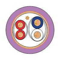
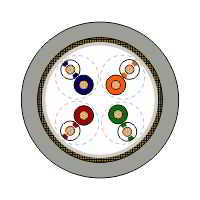
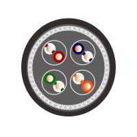
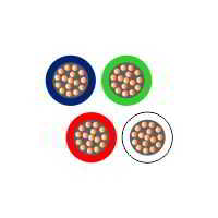
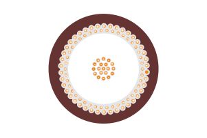
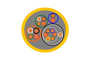
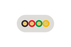
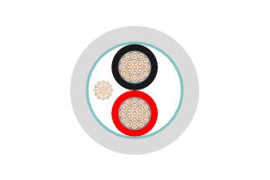
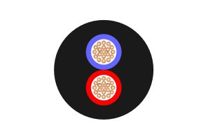
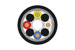
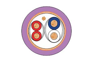
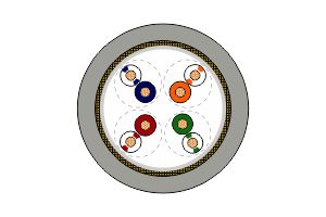
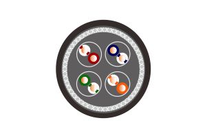
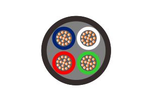
Core Identification: | |||||||||||||||||||
2 Core | Brown | Blue | |||||||||||||||||
3 Core | Brown | Black | Grey | ||||||||||||||||
3 Core | Brown | Blue | G/Y | ||||||||||||||||
4 Core | Brown | Black | Blue | Grey | |||||||||||||||
5 Core and above - up to 6mm² White | |||||||||||||||||||
2, 3, 4 or 5 Core 1.5 - 2.5mm² White | |||||||||||||||||||
Should not be installed at temperatures below 0°C or above +40°C
| |||||||||||||||||||
Dimensions(1.5mm²-16mm²): | |||||||||||||||||||
Zion Code | Conductor Size (mm2) | Stranding (mm) | No. Of | Weight Kg/km | Overall | Gland Size (mm) | Nylon | ||||||||||||
71504-2X1.5 | 1.5 | 7/0.53 | 2 | 234 | 11.06 | 20/16 | 0.5 | ||||||||||||
71504-3X1.5 | 1.5 | 7/0.53 | 3 | 271 | 11.54 | 20/16 | 0.5 | ||||||||||||
71504-4X1.5 | 1.5 | 7/0.53 | 4 | 306 | 12.26 | 20/16 | 0.5 | ||||||||||||
71504-5X1.5 | 1.5 | 7/0.53 | 5 | 356 | 13.23 | 20s | 0.6 | ||||||||||||
71504-7X1.5 | 1.5 | 7/0.53 | 7 | 391 | 14.10 | 20s | 0.6 | ||||||||||||
71504-8X1.5 | 1.5 | 7/0.53 | 8 | 501 | 16.70 | 20 | 0.7 | ||||||||||||
71504-10X1.5 | 1.5 | 7/0.53 | 10 | 650 | 18.00 | 20 | 0.8 | ||||||||||||
71504-12X1.5 | 1.5 | 7/0.53 | 12 | 657 | 18.30 | 20 | 0.8 | ||||||||||||
71504-19X1.5 | 1.5 | 7/0.53 | 19 | 863 | 20.78 | 25 | 0.9 | ||||||||||||
71504-27X1.5 | 1.5 | 7/0.53 | 27 | 1310 | 25.10 | 25 | 1.0 | ||||||||||||
71504-37X1.5 | 1.5 | 7/0.53 | 37 | 1590 | 27.50 | 32 | 1.1 | ||||||||||||
71504-48X1.5 | 1.5 | 7/0.53 | 48 | 1900 | 30.00 | 32 | 1.2 | ||||||||||||
71504-2X2.5 | 2.5 | 7/0.67 | 2 | 312 | 12.40 | 20s | 0.5 | ||||||||||||
71504-3X2.5 | 2.5 | 7/0.67 | 3 | 343 | 12.99 | 20s | 0.6 | ||||||||||||
71504-4X2.5 | 2.5 | 7/0.67 | 4 | 392 | 13.86 | 20s | 0.6 | ||||||||||||
71504-5X2.5 | 2.5 | 7/0.67 | 5 | 463 | 14.92 | 20s | 0.6 | ||||||||||||
71504-7X2.5 | 2.5 | 7/0. 67 | 7 | 509 | 15.96 | 20 | 0.8 | ||||||||||||
71504-10X2.5 | 2.5 | 7/0.67 | 10 | 850 | 20.00 | 25 | 0.8 | ||||||||||||
71504-12X2.5 | 2.5 | 7/0.67 | 12 | 861 | 21.11 | 25 | 0.9 | ||||||||||||
71504-19X2.5 | 2.5 | 7/0.67 | 19 | 1324 | 25.16 | 25 | 1.0 | ||||||||||||
71504-27X2.5 | 2.5 | 7/0.67 | 27 | 1760 | 30.00 | 32 | 1.2 | ||||||||||||
71504-37X2.5 | 2.5 | 7/0.67 | 37 | 2185 | 33.00 | 40 | 1.4 | ||||||||||||
71504-48X2.5 | 2.5 | 7/0.67 | 48 | 2800 | 36.00 | 40 | 1.6 | ||||||||||||
71504-2X4 | 4.0 | 7/0.85 | 2 | 373 | 13.38 | 20s | 0.6 | ||||||||||||
71504-3X4 | 4.0 | 7/0.85 | 3 | 421 | 14.05 | 20s | 0.6 | ||||||||||||
71504-4X4 | 4.0 | 7/0.85 | 4 | 496 | 15.04 | 20 | 0.6 | ||||||||||||
71504-5X4 | 4.0 | 7/0.85 | 5 | 573 | 16.35 | 20 | 0.7 | ||||||||||||
71504-7X4 | 4.0 | 7/0.85 | 7 | 741 | 18.21 | 20 | 0.8 | ||||||||||||
71504-12X4 | 4.0 | 7/0.85 | 12 | 1255 | 24.24 | 25 | 1.0 | ||||||||||||
71504-19X4 | 4.0 | 7/0.85 | 19 | 1690 | 27.61 | 32 | 1.1 | ||||||||||||
71504-27X4 | 4.0 | 7/0.85 | 27 | 2250 | 32.00 | 32 | 1.4 | ||||||||||||
71504-2X6 | 6.0 | 7/1.04 | 2 | 450 | 14.38 | 20s | 0.6 | ||||||||||||
71504-3X6 | 6.0 | 7/1.04 | 3 | 515 | 15.14 | 20 | 0.7 | ||||||||||||
71504-4X6 | 6.0 | 7/1.04 | 4 | 696 | 17.03 | 20 | 0.7 | ||||||||||||
71504-5X6 | 6.0 | 7/1.04 | 5 | 808 | 18. 39 | 20 | 0.8 | ||||||||||||
71504-7X6 | 6.0 | 7/1.04 | 7 | 1100 | 21.90 | 25 | 0.9 | ||||||||||||
71504-2X10 | 10.0 | 7/1.35 | 2 | 590 | 16.18 | 20 | 0.7 | ||||||||||||
71504-3X10 | 10.0 | 7/1.35 | 3 | 781 | 17.76 | 20 | 0.8 | ||||||||||||
71504-4X10 | 10.0 | 7/1.35 | 4 | 927 | 19.09 | 25 | 0.8 | ||||||||||||
71504-5X10 | 10.0 | 7/1.35 | 5 | 1095 | 20.91 | 25 | 0.9 | ||||||||||||
71504-7X10 | 10.0 | 7/1.35 | 7 | 1500 | 25.00 | 25 | 1.0 | ||||||||||||
71504-2X16 | 16.0 | 7/1.70 | 2 | 893 | 19.06 | 25 | 0.8 | ||||||||||||
71504-3X16 | 16.0 | 7/1.70 | 3 | 1059 | 20.35 | 25 | 0.9 | ||||||||||||
71504-4X16 | 16.0 | 7/1.70 | 4 | 1269 | 21.95 | 25 | 0.9 | ||||||||||||
71504-5X16 | 16.0 | 7/1.70 | 5 | 1679 | 25.19 | 25 | 1.1 | ||||||||||||
71504-7X16 | 16.0 | 7/1.70 | 7 | 2150 | 28.10 | 32 | 1.2 | ||||||||||||
Current Carrying (amperes) | |||||||||||||||||||
CONDUCTOR CROSS | REFERENCE METHOD C | REFERENCE METHOD E | REFERENCE METHOD D | ||||||||||||||||
1 TWO CORE CABLE | 1 THREE OR | 1 TWO CORE CABLE SINGLE-PHASE | 1 THREE OR | 1 TWO CORE CABLE SINGLE-PHASE | 1 THREE OR | ||||||||||||||
1 | 2 | 3 | 4 | 5 | 6 | 7 | |||||||||||||
(MM²) | (A) | (A) | (A) | (A) | (A) | (A) | |||||||||||||
2 | 27 | 23 | 29 | 25 | 25 | 21 | |||||||||||||
3 | 36 | 31 | 39 | 33 | 33 | 28 | |||||||||||||
4 | 49 | 42 | 52 | 44 | 43 | 36 | |||||||||||||
6 | 62 | 53 | 66 | 56 | 53 | 44 | |||||||||||||
10 | 85 | 73 | 90 | 78 | 71 | 58 | |||||||||||||
16 | 110 | 94 | 115 | 99 | 91 | 75 | |||||||||||||
Voltage Drop | |||||||||||||||||||
NOMINAL CROSS SECTIONAL | TWO CORE CABLE DC | TWO CORE CABLE SINGLE-PHASE AC | THREE OR FOUR CORE CABLE | ||||||||||||||||
(MM²) | (MV/A /M) | (MV/A/M) | (MV/A/M) | ||||||||||||||||
1.5 | 31 | 31 | 27 | ||||||||||||||||
2.5 | 19 | 19 | 16 | ||||||||||||||||
4 | 12 | 12 | 10 | ||||||||||||||||
6 | 7.9 | 7.9 | 6.8 | ||||||||||||||||
10 | 4.7 | 4.7 | 6.8 | ||||||||||||||||
16 | 2.9 | 2.9 | 2.5 | ||||||||||||||||