Cable & Wire | Good quality and good service based on reasonable prices.
 |

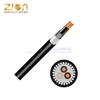

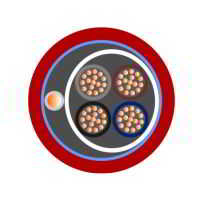
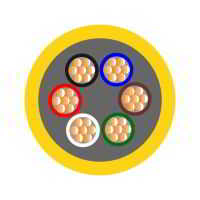
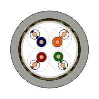
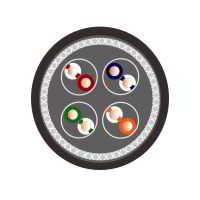
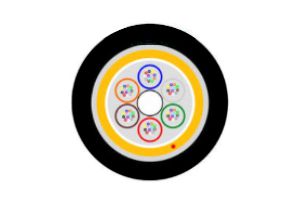
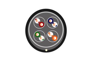
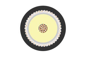
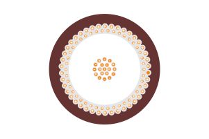
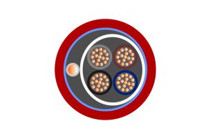
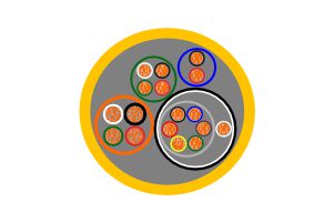
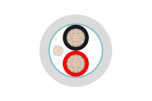
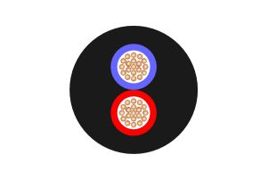
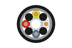
CU/XLPE/LSZH/SWA/LSZH 0.6/1KV Cable(25mm²-400mm²)
hellosignal
Product Description
CU/XLPE/LSZH/SWA/LSZH 0.6/1KV Cable(25mm²-400mm²) | |||||||||||||||||||
| |||||||||||||||||||
Application: | Cable Standards: | ||||||||||||||||||
Used in power networks, indoor, outdoor, | BS6724, Acid gas emission to BS EN 50267 (IEC 60754-1) | ||||||||||||||||||
Smoke emission to BS EN 50268 (IEC 61034) | |||||||||||||||||||
Flame propagation: IEC 60332-1, IEC60332-3, | |||||||||||||||||||
Product Description: | |||||||||||||||||||
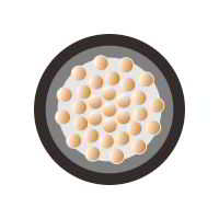
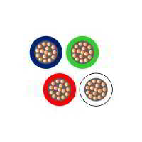
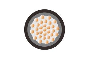
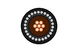
Conductor | Plain Annealed Stranded Copper Conductors | ||||||||||||||||||
Insulation | Cross linked Polyethylene (XLPE) | ||||||||||||||||||
Bedding | LSZH | ||||||||||||||||||
Armour | Steel Wire Armour (SWA) | ||||||||||||||||||
Sheath | Low Smoke and Zero Halogen | ||||||||||||||||||
Characteristics: | |||||||||||||||||||
Voltage Rating | 600/1000 Volts | ||||||||||||||||||
Temperature Limits | -15°C to +90°C | ||||||||||||||||||
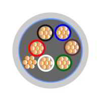
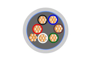
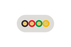
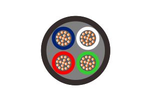
Core Identification: | |||||||||||||||||||
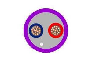
2 Core | Brown | Blue | |||||||||||||||||
3 Core | Brown | Black | Grey | ||||||||||||||||
3 Core | Brown | Blue | G/Y | ||||||||||||||||
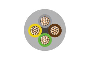
4 Core | Brown | Black | Blue | Grey | |||||||||||||||
5 Core and above - up to 6mm² White | |||||||||||||||||||
Should not be installed at temperatures below 0°C or above +40°C
| |||||||||||||||||||
Dimensions(25mm²-400mm²): | |||||||||||||||||||
Zion Code | Conductor Size (mm2) | Stranding (mm) | No. Of | Weight Kg/km | Overall | Gland Size (mm) | Nylon | ||||||||||||
71504-2×25 | 25.0 | 7/2.14 | 2 | 1050 | 20.00 | 25 | 0.8 | ||||||||||||
71504-3×25 | 25.0 | 7/2.14 | 3 | 1500 | 23.00 | 25 | 1.0 | ||||||||||||
71504-4×25 | 25.0 | 7/2.14 | 4 | 1800 | 25.00 | 32 | 1.0 | ||||||||||||
71504-5×25 | 25.0 | 7/2.14 | 5 | 2200 | 29.00 | 32 | 1.2 | ||||||||||||
71504-2×35 | 35.0 | 7/2.52 | 2 | 1400 | 22.00 | 25 | 0.9 | ||||||||||||
71504-3×35 | 35.0 | 7/2.52 | 3 | 1800 | 26.00 | 32 | 1.1 | ||||||||||||
71504-4×35 | 35.0 | 7/2.52 | 4 | 2200 | 28.00 | 32 | 1.2 | ||||||||||||
71504-5×35 | 35.0 | 7/2.52 | 5 | 2800 | 33.00 | 40 | 1.4 | ||||||||||||
71504-2×50 | 50.0 | 19/1.78 | 2 | 1750 | 25.00 | 32 | 1.0 | ||||||||||||
71504-3×50 | 50.0 | 19/1.78 | 3 | 2250 | 28.00 | 32 | 1.2 | ||||||||||||
71504-4×50 | 50.0 | 19/1.78 | 4 | 2850 | 31.00 | 32 | 1.4 | ||||||||||||
71504-5×50 | 50.0 | 19/1.78 | 5 | 3850 | 38.00 | 40 | 1.6 | ||||||||||||
71504-2×70 | 70.0 | 19/2.14 | 2 | 2200 | 28.00 | 32 | 1.2 | ||||||||||||
71504-3×70 | 70.0 | 19/2.14 | 3 | 3000 | 32.00 | 32 | 1.4 | ||||||||||||
71504-4×70 | 70.0 | 19/2.14 | 4 | 4100 | 37.00 | 40 | 1.6 | ||||||||||||
71504-5×70 | 70.0 | 19/2.14 | 5 | 5100 | 43.00 | 50s | 1.8 | ||||||||||||
71504-2×95 | 95.0 | 19/2.52 | 2 | 3000 | 32.00 | 40 | 1.4 | ||||||||||||
71504-3×95 | 95.0 | 19/2.52 | 3 | 4150 | 37.00 | 40 | 1.6 | ||||||||||||
71504-4×95 | 95.0 | 19/2.52 | 4 | 5200 | 40.00 | 50s | 1.8 | ||||||||||||
71504-5×95 | 95.0 | 19/2.52 | 5 | 7700 | 52.00 | 50 | TC9 | ||||||||||||
71504-2×120 | 120.0 | 37/2.03 | 2 | 3600 | 35.00 | 40 | 1.4 | ||||||||||||
71504-3×120 | 120.0 | 37/2.03 | 3 | 4950 | 40.00 | 50s | 1.8 | ||||||||||||
71504-4×120 | 120.0 | 37/2.03 | 4 | 6700 | 46.00 | 50 | 2.0 | ||||||||||||
71504-5×120 | 120.0 | 37/2.03 | 5 | 9030 | 57.00 | 63S | TC9 | ||||||||||||
71504-2×150 | 150.0 | 37/2.25 | 2 | 4250 | 37.00 | 40 | 1.6 | ||||||||||||
71504-3×150 | 150.0 | 37/2.25 | 3 | 6300 | 45.00 | 50 | 1.8 | ||||||||||||
71504-4×150 | 150.0 | 37/2.25 | 4 | 7900 | 49.00 | 50 | 2.0 | ||||||||||||
71504-5×150 | 150.0 | 37/2.25 | 5 | 10430 | 61.00 | 63 | TC11 | ||||||||||||
71504-2×185 | 185.0 | 37/2.52 | 2 | 5500 | 43.00 | 50 | 1.8 | ||||||||||||
71504-3×185 | 185.0 | 37/2.52 | 3 | 7650 | 49.00 | 50 | 2.0 | ||||||||||||
71504-4×185 | 185.0 | 37/2.52 | 4 | 9650 | 55.00 | 63S | TC9 | ||||||||||||
71504-2×240 | 240.0 | 61/2.25 | 2 | 6900 | 48.00 | 50 | 2.0 | ||||||||||||
71504-3×240 | 240.0 | 61/2.25 | 3 | 9650 | 56.00 | 63S | TC9 | ||||||||||||
71504-4×240 | 240.0 | 61/2.25 | 4 | 12400 | 62.00 | 63 | TC10 | ||||||||||||
71504-2×300 | 300.0 | 61/2.52 | 2 | 8200 | 50.00 | 50 | 2.0 | ||||||||||||
71504-3×300 | 300.0 | 61/2.52 | 3 | 11550 | 59.00 | 63 | TC10 | ||||||||||||
71504-4×300 | 300.0 | 61/2.52 | 4 | 14800 | 66.00 | 75S | TC11 | ||||||||||||
71504-2×400 | 400.0 | 61/2.85 | 2 | 10100 | 56.00 | 63S | TC9 | ||||||||||||
71504-3×400 | 400.0 | 61/2.85 | 3 | 14350 | 65.00 | 75S | TC11 | ||||||||||||
71504-4×400 | 400.0 | 61/2.85 | 4 | 19300 | 76.60 | 75 | TC14 | ||||||||||||
Current Carrying (amperes) | |||||||||||||||||||
CONDUCTOR CROSS | REFERENCE METHOD C | REFERENCE METHOD E | REFERENCE METHOD D | ||||||||||||||||
1 TWO CORE CABLE | 1 THREE OR | 1 TWO CORE CABLE SINGLE-PHASE | 1 THREE OR | 1 TWO CORE CABLE SINGLE-PHASE | 1 THREE OR | ||||||||||||||
1 | 2 | 3 | 4 | 5 | 6 | 7 | |||||||||||||
(MM²) | (A) | (A) | (A) | (A) | (A) | (A) | |||||||||||||
25 | 146 | 124 | 152 | 131 | 116 | 96 | |||||||||||||
35 | 180 | 154 | 188 | 162 | 139 | 115 | |||||||||||||
50 | 219 | 187 | 228 | 197 | 164 | 135 | |||||||||||||
70 | 279 | 238 | 291 | 251 | 203 | 167 | |||||||||||||
95 | 338 | 289 | 354 | 304 | 239 | 197 | |||||||||||||
120 | 392 | 335 | 410 | 353 | 271 | 223 | |||||||||||||
150 | 451 | 386 | 472 | 406 | 306 | 251 | |||||||||||||
185 | 515 | 441 | 539 | 463 | 343 | 281 | |||||||||||||
240 | 607 | 520 | 636 | 546 | 395 | 324 | |||||||||||||
300 | 698 | 599 | 732 | 628 | 446 | 365 | |||||||||||||
400 | 787 | 673 | 847 | 728 | - | - | |||||||||||||
Voltage Drop | |||||||||||||||||||
NOMINAL CROSS SECTIONAL AREA MM² | TWO CORE CABLE DC | TWO CORE CABLE SINGLE-PHASE AC | THREE OR FOUR CORE CABLE | ||||||||||||||||
(MM²) | (MV/A/M) | (MV/A/M) | (MV/A/M) | ||||||||||||||||
R | X | Z | R | X | Z | ||||||||||||||
25 | 1.850 | 1.850 | 0.160 | 1.900 | 1.600 | 0.140 | 1.650 | ||||||||||||
35 | 1.350 | 1.350 | 0.155 | 1.350 | 1.150 | 0.135 | 1.150 | ||||||||||||
50 | 0.980 | 0.990 | 0.155 | 1.000 | 0.866 | 0.135 | 0.870 | ||||||||||||
70 | 0.670 | 0.670 | 0.150 | 0.690 | 0.590 | 0.130 | 0.600 | ||||||||||||
95 | 0.490 | 0.500 | 0.150 | 0.520 | 0.430 | 0.130 | 0.450 | ||||||||||||
120 | 0.390 | 0.400 | 0.415 | 0.420 | 0.340 | 0.130 | 0.370 | ||||||||||||
150 | 0.310 | 0.320 | 0.145 | 0.350 | 0.280 | 0.125 | 0.300 | ||||||||||||
185 | 0.250 | 0.260 | 0.145 | 0.290 | 0.220 | 0.125 | 0.260 | ||||||||||||
240 | 0.195 | 0.200 | 0.140 | 0.240 | 0.175 | 0.125 | 0.210 | ||||||||||||
300 | 0.155 | 0.150 | 0.140 | 0.210 | 0.140 | 0.120 | 0.185 | ||||||||||||
400 | 0.120 | 0.130 | 0.140 | 0.190 | 0.115 | 0.120 | 0.165 | ||||||||||||