Cable & Wire | Good quality and good service based on reasonable prices.
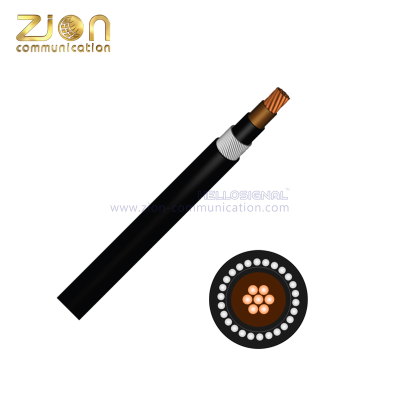 |


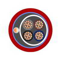
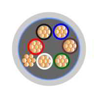
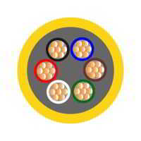
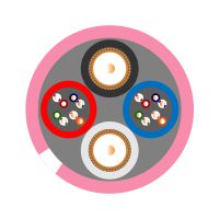
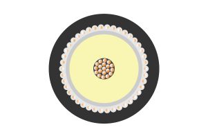
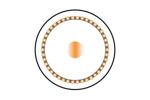
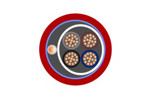
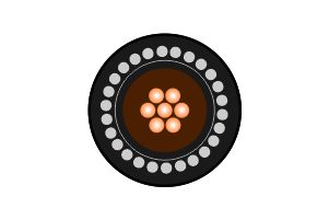
CU/XLPE/PVC/AWA/PVC 0.6/1KV Cable
hellosignal
Product Description
CU/XLPE/PVC/AWA/PVC 0.6/1KV Cable | |||||||||||||||||||
| |||||||||||||||||||
Application: | Cable Standards: | ||||||||||||||||||
General single core PVC cable with aluminium wire armour(AWA) | Flame propagation to BS EN 60332-1-2 | ||||||||||||||||||
BS5467 | |||||||||||||||||||
IEC/EN 60228 | |||||||||||||||||||
Product Description: | |||||||||||||||||||
Conductor | Stranded Plain Annealed Circular Copper Conductor | ||||||||||||||||||
Insulation | Cross Linked Polyethylene (XLPE) | ||||||||||||||||||
Bedding | PVC | ||||||||||||||||||
Armour | Aluminium Wire | ||||||||||||||||||
Sheath | PVC | ||||||||||||||||||
Characteristics: | |||||||||||||||||||
Voltage Rating | 600/1000 Volts | ||||||||||||||||||
Temperature Limits | -15°C to +90°C | ||||||||||||||||||
Core Identification: | |||||||||||||||||||
Brown Inner | |||||||||||||||||||
Should not be installed at temperatures below 0°C or above +60°C
| |||||||||||||||||||
Dimensions: | |||||||||||||||||||
Zion Code | Conductor Size (mm2) | Stranding (mm) | No. Of | Weight Kg/km | Overall | Brass | Nylon | Nylon | Trefoil | ||||||||||
71501-50 | 50 | 19/1.78 | 1 | 638 | 17.70 | 20 | 25 | 0.7 | - | ||||||||||
71501-70 | 70 | 19/2.14 | 1 | 891 | 19.60 | 25 | 32 | 0.8 | - | ||||||||||
71501-95 | 95 | 19/2.52 | 1 | 1166 | 21.50 | 25 | 32 | 0.9 | - | ||||||||||
71501-120 | 120 | 37/2.03 | 1 | 1412 | 23.10 | 25 | 32 | 1.0 | - | ||||||||||
71501-150 | 150 | 37/2.25 | 1 | 1800 | 26.00 | 32 | 40 | 1.1 | - | ||||||||||
71501-185 | 185 | 37/2.52 | 1 | 2200 | 28.00 | 32 | 40 | 1.2 | TASB04 | ||||||||||
71501-240 | 240 | 61/2.25 | 1 | 2800 | 32.00 | 40 | 50S | 1.4 | TASB06 | ||||||||||
71501-300 | 300 | 61/2.52 | 1 | 3400 | 33.00 | 40 | 50S | 1.4 | TASB06 | ||||||||||
71501-400 | 400 | 61/2.85 | 1 | 4450 | 38.00 | 40 | 50 | 1.6 | TASB10 | ||||||||||
71501-500 | 500 | 61/3.2 | 1 | 5550 | 43.00 | 50S | 63S | 1.8 | TASB13 | ||||||||||
71501-630 | 630 | 127/2.52 | 1 | 7100 | 47.00 | 50 | 63S | 2.0 | TASB15 | ||||||||||
Current Carrying Capacity: | |||||||||||||||||||
THE ABOVE IS IN ACCORDANCE WITH 18TH EDITION OF IET WIRING REGULATIONS | |||||||||||||||||||
CONDUCTOR CROSS – SECTIONAL AREA | REFERENCE METHOD C (CLIPPED DIRECT) | REFERENCE METHOD F (IN FREE AIR ON A PERFORATED CABLE TRAY HORIZONTAL / VERTICAL) | |||||||||||||||||
TOUCHING | TOUCHING | SPACED BY ONE DIAMETER | |||||||||||||||||
2 CABLES, SINGLE - PHASE AC OR DC FLAT | 3 OR 4 | 2 CABLES, SINGLE - PHASE AC OR DC FLAT | 3 CABLES, | 3 CABLES, THREE - PHASE AC TREFOIL | 2 CABLES DC | 2 CABLES, SINGLE PHASE AC | 3 OR 4 CABLES, | ||||||||||||
HORIZONTAL | VERTICAL | HORIZONTAL | VERTICAL | HORIZONTAL | VERTICAL | ||||||||||||||
1 | 2 | 3 | 4 | 5 | 6 | 7 | 8 | 9 | 10 | 11 | 12 | ||||||||
(MM²) | (A) | (A) | (A) | (A) | (A) | (A) | (A) | (A) | (A) | (A) | (A) | ||||||||
50 | 237 | 220 | 253 | 232 | 222 | 284 | 270 | 282 | 266 | 288 | 266 | ||||||||
70 | 303 | 277 | 322 | 293 | 285 | 356 | 349 | 357 | 337 | 358 | 331 | ||||||||
95 | 367 | 333 | 389 | 352 | 346 | 446 | 426 | 436 | 412 | 425 | 393 | ||||||||
120 | 425 | 383 | 449 | 405 | 402 | 519 | 497 | 504 | 477 | 485 | 449 | ||||||||
150 | 488 | 437 | 516 | 462 | 463 | 600 | 575 | 566 | 539 | 549 | 510 | ||||||||
185 | 557 | 496 | 587 | 524 | 529 | 688 | 660 | 643 | 614 | 618 | 574 | ||||||||
240 | 656 | 579 | 689 | 612 | 625 | 815 | 782 | 749 | 714 | 715 | 666 | ||||||||
300 | 755 | 662 | 792 | 700 | 720 | 943 | 906 | 842 | 805 | 810 | 755 | ||||||||
400 | 853 | 717 | 899 | 767 | 815 | 1137 | 1094 | 929 | 889 | 848 | 797 | ||||||||
500 | 962 | 791 | 1016 | 851 | 918 | 1314 | 1266 | 1032 | 989 | 923 | 871 | ||||||||
630 | 1082 | 861 | 1146 | 935 | 1027 | 1528 | 1474 | 1139 | 1092 | 992 | 940 | ||||||||
Voltage Drop | |||||||||||||||||||
CONDUCTOR CROSS – SECTIONAL AREA | 2 CABLES DC | REFERENCE METHODS C AND F (CLIPPED DIRECT, ON TRAY OR IN FREE AIR) | |||||||||||||||||
2 CABLES SINGLE PASS AC | 3 OR 4 CABLES THREE PHASE AC | ||||||||||||||||||
TOUCHING | SPACED | TREFOIL / TOUCHING | FLAT / TOUCHING | FLAT / SPACED | |||||||||||||||
R | X | Z | R | X | Z | R | X | Z | R | X | Z | R | X | Z | |||||
50 | 0.980 | 0.990 | 0. 210 | 1.000 | 0.980 | 0.290 | 1.000 | 0.86 | 0.180 | 0. 870 | 0.840 | 0.250 | 0.880 | 0.840 | 0.330 | 0.90 | |||
70 | 0.670 | 0.680 | 0.200 | 0.710 | 0.690 | 0.290 | 0.750 | 0.59 | 0.170 | 0.620 | 0.600 | 0.250 | 0.650 | 0.620 | 0.320 | 0.70 | |||
95 | 0.490 | 0. 510 | 0.195 | 0.550 | 0.530 | 0.280 | 0.600 | 0.44 | 0.170 | 0. 470 | 0.460 | 0.240 | 0. 52 | 0.490 | 0. 310 | 0.58 | |||
120 | 0.390 | 0. 410 | 0.190 | 0.450 | 0.430 | 0.270 | 0. 51 | 0.35 | 0.165 | 0.390 | 0.380 | 0.240 | 0.440 | 0. 410 | 0.300 | 0. 51 | |||
150 | 0. 310 | 0.330 | 0.185 | 0.380 | 0.360 | 0.270 | 0.450 | 0.29 | 0.160 | 0.330 | 0. 310 | 0.230 | 0.390 | 0.340 | 0.290 | 0.45 | |||
185 | 0.250 | 0. 270 | 0.185 | 0.330 | 0.300 | 0.260 | 0.400 | 0.23 | 0.160 | 0.280 | 0.260 | 0.230 | 0.340 | 0.290 | 0.290 | 0. 41 | |||
240 | 0.195 | 0. 210 | 0.180 | 0.280 | 0.240 | 0.260 | 0.350 | 0.18 | 0.155 | 0.240 | 0. 210 | 0.220 | 0.300 | 0.240 | 0.280 | 0.37 | |||
300 | 0.155 | 0.170 | 0.175 | 0.250 | 0.195 | 0.250 | 0.320 | 0.145 | 0.150 | 0. 210 | 0.170 | 0.220 | 0.280 | 0.200 | 0. 270 | 0.34 | |||
400 | 0. 115 | 0.145 | 0.170 | 0.220 | 0.180 | 0. 24 | 0.300 | 0.125 | 0.150 | 0.195 | 0.160 | 0. 210 | 0.270 | 0.200 | 0. 270 | 0.33 | |||
500 | 0.093 | 0.125 | 0.170 | 0.210 | 0.165 | 0. 24 | 0.290 | 0.105 | 0.145 | 0.180 | 0.145 | 0.200 | 0.250 | 0.190 | 0.240 | 0. 31 | |||
630 | 0.073 | 0.105 | 0.165 | 0.195 | 0.150 | 0.230 | 0.270 | 0.092 | 0.145 | 0.170 | 0.135 | 0.195 | 0. 24 | 0.175 | 0.230 | 0.29 | |||
The Above Is In Accordance With 18th Edition Of Iet Wiring Regulations | |||||||||||||||||||